Industry Information
Rubber-to-Metal Bonded Seal Inspection: What to Check
Bonded washers and cased seals add failure modes the rubber defect list does not name - what the camera covers, what metal-side criteria to write, and why bond adhesion is a lab question.
The Part Where Two Materials Meet
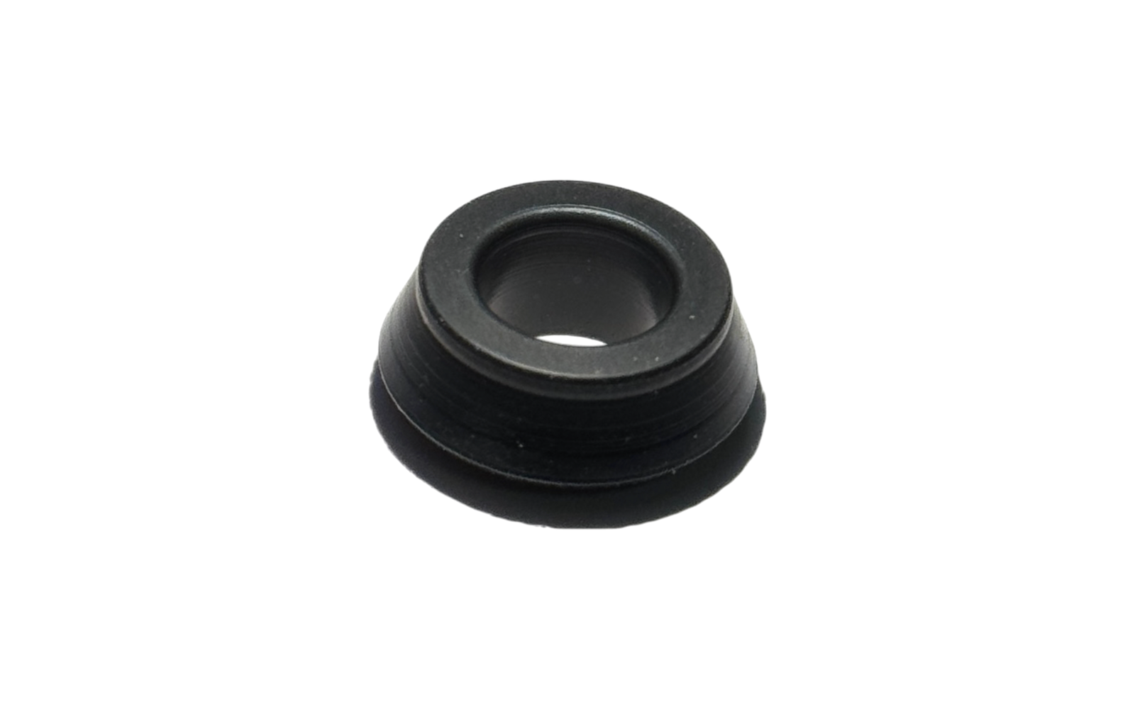
A rubber-to-metal bonded part - a bonded washer (often called a Dowty washer), a cased oil seal, an insert-molded fitting - puts two inspection problems in one component. The rubber half fails in the families every molded seal fails in; the metal half fails in ways that list does not name: rubber that did not fully cover the insert, an insert that shifted in the mold, metal dents and corrosion from handling. And between the two sits the joint itself - the adhesion - which is the failure mode buyers care about most and the one a surface camera cannot measure. This article splits those three clearly: what the standard families cover on the rubber side, what criteria the metal side needs you to write, and why the adhesion question belongs to a different instrument class entirely. The closest published cousin is the oil seal guide (/posts/oil-seal-inspection-machine) - a cased seal is one bonded family; this article covers the family as a whole.
What the Standard Families Cover
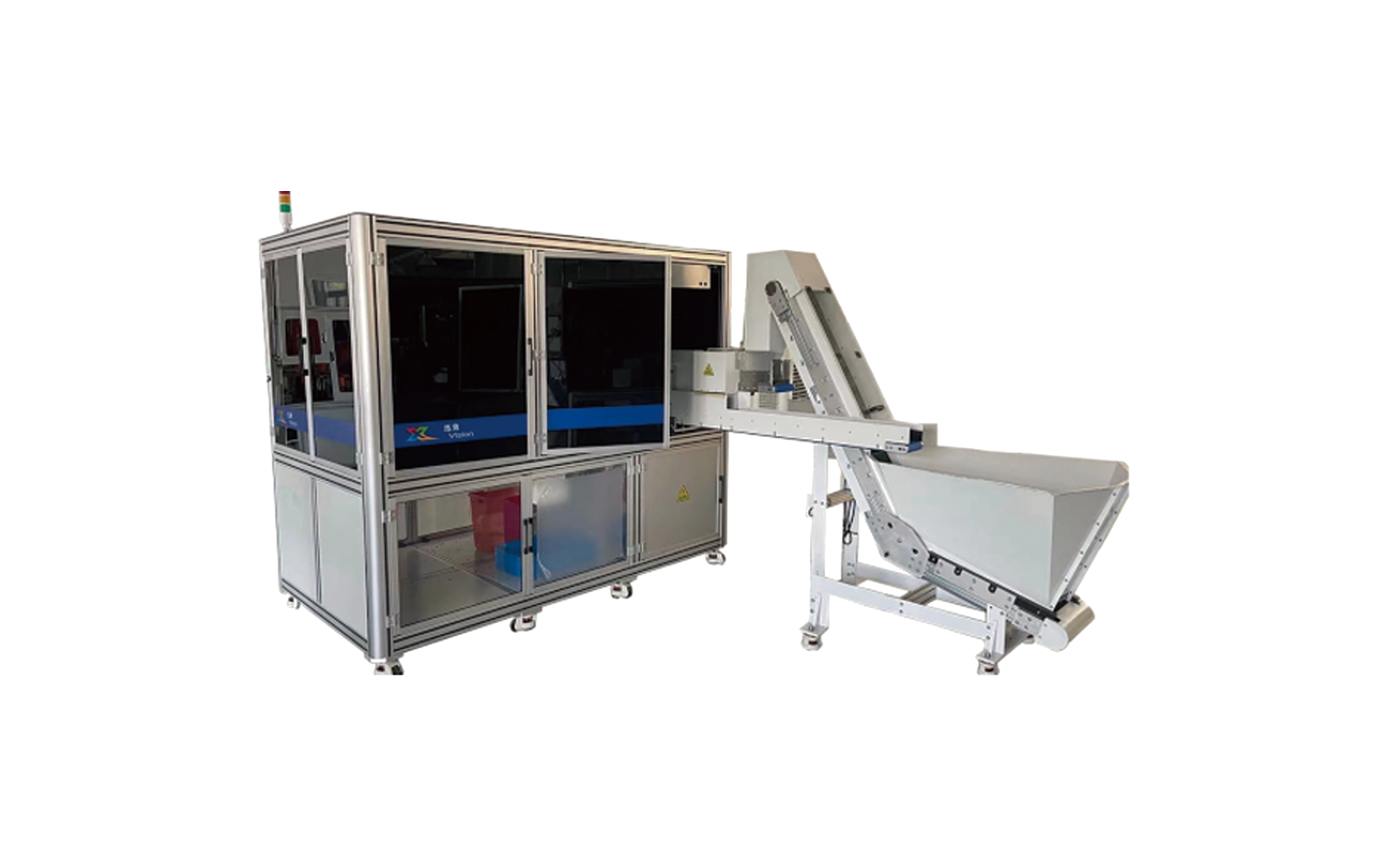
The turntable machines list automotive parts, precision hardware and oil seals among their brochure targets, and they check appearance through the standard families: short shots (non-fill), pits, blocked holes, cracks, damage, burrs, mold residue, flow marks, impurities, scratches, dents and contamination. Dimensional checks run on ID, OD and cross-section, with thickness measurable with added cameras - confirmed in the tested configuration. On the rubber surface of a bonded part, those families apply unchanged: the rubber can short-shot, flash at the joint line, carry flow marks, or sit under-filled exactly where it matters. The size bands still govern - 6-120 mm OD on the dual-table machine and 6-80 mm on the single-table models, thickness limits per the brochure - and the by-size guide (/posts/o-ring-inspection-machine-by-size) maps them.
What the Metal Side Adds
The metal-side failure modes are real, they cause claims, and they are not in the rubber defect list - which means they only get checked if you write them as explicit criteria:
• Incomplete rubber coverage: bare metal spots where compound failed to wet the insert. Visually a surface question - but only if "no visible bare metal at the joint line" is stated as a rule, with a size threshold, because a speck and a bare band are different decisions. Where to draw that size line is a false reject / false accept decision in itself - the trade-off is covered in false rejects and false accepts (/posts/false-rejects-false-accepts-inspection).
• Insert displacement: the insert out of position or tilted, which shifts the sealing geometry even when every rubber dimension reads in tolerance. Dimensional checks catch what they measure; the criteria decide which measurements bind.
• Metal damage: dents, scratches and corrosion on the case or flange - handling and storage failures like any metal part's. These are appearance rules on the metal face, and they belong in your criteria list explicitly, because the machine will not invent them.
The method for writing these into a specification is the same one in defining defects for OK/NG inspection (/posts/defining-defects-ai-visual-inspection): name the family, set the severity line, mark limit samples for each.
The Boundary: Bond Adhesion Is Not a Camera Question
The failure mode that matters most on a bonded part - rubber separating from metal in service - is a bond-strength property. It is measured by destructive laboratory tests on sampled parts - the pull-off and peel methods in the standard adhesion-test families - not by looking at the surface. What a camera sees of the bond is indirect: the joint line's appearance, rubber coverage at the edge, gross signs like visible separation or exposed metal. A vision inspection machine screens the population for appearance signals; it does not certify adhesion, and no honest inspection list claims to. If adhesion is on your customer's criteria, it is answered by the lab test regime on sampled parts - with the appearance machine catching the visible extremes (bare spots, gross separation) in between the lab's samples. The purchase-boundary guide (/posts/when-not-to-buy-vision-inspection-machine) makes the general point: check how much of your risk is surface-visible before buying cameras for it.
What Only the Sample Test Settles
• Joint-line visibility: how clearly the rubber-metal boundary presents on your parts in the natural rest position - the criteria above are only configurable if the line is actually visible to the cameras.
• Metal-side rules: whether your written criteria for bare spots, insert position and metal damage map to configuration rules that behave consistently across your lots.
• Rest orientation and feeding: a metal insert changes how a part sits and feeds compared with an all-rubber one - and how the feeding method treats plated or phosphated metal faces matters, because a coating scratched in feeding is a corrosion claim waiting to happen. Both are confirmed on your parts, per the five feeding options (/posts/vision-inspection-machine-feeder-types) and the sample-test process in the walkthrough (/posts/vision-inspection-sample-test).
Frequently Asked Questions
Can the machine check bond strength?
No - bond adhesion is a destructive laboratory measurement on sampled parts (pull-off and peel test methods). The camera screens for appearance signals around the joint (bare metal, gross separation); it does not measure adhesion.
We see exposed metal on some parts - is that checkable?
As an explicit appearance rule, yes - "no visible bare metal at the joint line, up to size X" is a surface question like any other. It needs your criteria and limit samples; the machine does not invent the threshold.
Is a cased oil seal a bonded part?
Yes - the case-and-lip structure makes it the most familiar bonded family, and it has its own guide at oil seal inspection (/posts/oil-seal-inspection-machine), including the garter-spring boundary.
What about internal defects in the metal insert?
Internal metal defects and bond integrity below the surface are outside appearance-camera scope - they belong to lab and instrument methods. The brochure lists an X-ray inspection machine for oil seals, bearings and gears as non-standard customization - that instrument class, not the appearance camera, is where sub-surface questions belong.
Next Step
Write the metal-side criteria into your defect specification - coverage, insert position, metal damage - and mark limit samples for each, then send your bonded parts with the drawings. Confidentiality, test cycle and logistics for your samples are confirmed when you first contact the team. The sample test returns the images and OK/NG decision log showing what the configuration catches on your parts. Contact the team (/contact-us) - Monica (+86 138 5726 5705, WhatsApp) or Arya (+86 173 2430 9735), or email monica@aivisioncheck.com.